MotoCan Installation for KTM [LR0445]
How to install the MotoCAN for KTM Bikes

Installation Guide:
This is a step by step guide to installing the MotoCAN for KTM Bikes. There are two (2) types of systems for KTM. MotoCAN only supports one (1) type. A summary of model support for each of the MotoCAN can be found below.
If you are unsure about model support, check your VIN using our VIN Decoder here.
If there is no MotoCAN developed for Motorcycle Lights currently, any bike specific Gen2 ezCAN that has a minimum of v2408 release software will work with Motorcycle Lights. You can order a HEX ezCAN via the official distributor network to power the Motorcycle Lights.
MotoCAN for KTM Bikes
The NEW MotoCAN for KTM Bikes, supports the following models:
- KTM 1290 (2021+)
- KTM 890 (partial support)
- KTM 790 (partial support)
These are KTMs that feature the (red) EURO5 CAN-bus connector.
Due to limitation of the 890 wiring harness, these models have the following limitations:
- Auxiliary Brake functionality on Front brake activation only
- No support for toggling aux lights on/off
- No support for Turn signals
- No support for switching Auxiliary front lights off or flash them with Turn signals active
- No support for Run/Brake/Turn signal functionality
- No support for Heated gear
STEP 1:
Install your MotoCAN on your Motorcycle
LOCATE YOUR BIKE'S BATTERY & DIAGNOSTIC PLUG
Find the battery and diagnostic connector under the seat or under the battery cover. Refer to your bike’s user manual for the exact location.
STEP 2:
INSTALL THE MotoCAN UNDER THE SEAT
You will be installing your MotoCAN under the seat. You can secure the MotoCAN with the velcro strips provided after the accessories have been plugged in.

STEP 3:
ROUTE AND CONNECT THE BATTERY WIRES
Route both the MotoCAN power supply cables forward to the battery. Disconnect the battery wiring harness terminals from the battery and connect the MotoCAN wires to the battery before re-connecting the factory wires.
IMPORTANT NOTE: First, unplug the battery negative wire and only attach it at the end again. This is good practice whenever you work on your bike’s electronics.

STEP 4:
PLUG THE MotoCAN INTO THE DIAGNOSTIC PORT
- Unplug the cap from the bike’s diagnostic port.
- Plug the HEX MotoCAN vehicle harness into the bike’s diagnostic port.
IMPORTANT NOTE: Do not connect the MotoCAN to any other similar looking connector or to any other part of the motorcycle’s wiring harness. If you do, the MotoCAN will not function


STEP 5:
CONNECT Motorcycle Lights to the White Channel

ADD OTHER ACCESSORIES USING COLOUR CODING
- 3 x Two wire stub connectors (Orange)
- 3 x Terminal Wires (Orange)
- 3 x Blanking seals
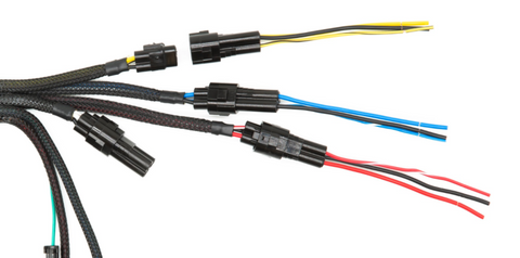
If your auxiliary lights have three wires change the two-wire stub connector into a three-wire see the image below. If your auxiliary lights have two wires use the two-wire stub connectors for accessories that have power and ground wires only.
If you are not going to use one or more of the circuit functions it is recommended that you install a blanking plug over the unused output. The MotoCAN product contains three blanking plugs.

Insert blanking seal to use as a two-wire stub connector
Insert terminal wire to use as a three-wire stub connector


Connect the terminals of the high-power stub connectors to the correct female terminals on the MotoCAN.
Connect the spotlight’s ground wire to the ground wire of the stub connector.
If you are installing spotlights equipped with a third wire for light-intensity control, connect the spotlight control wire to the control wire of the stub connector. If the spotlight only has two wires, use the two wire stub connectors.

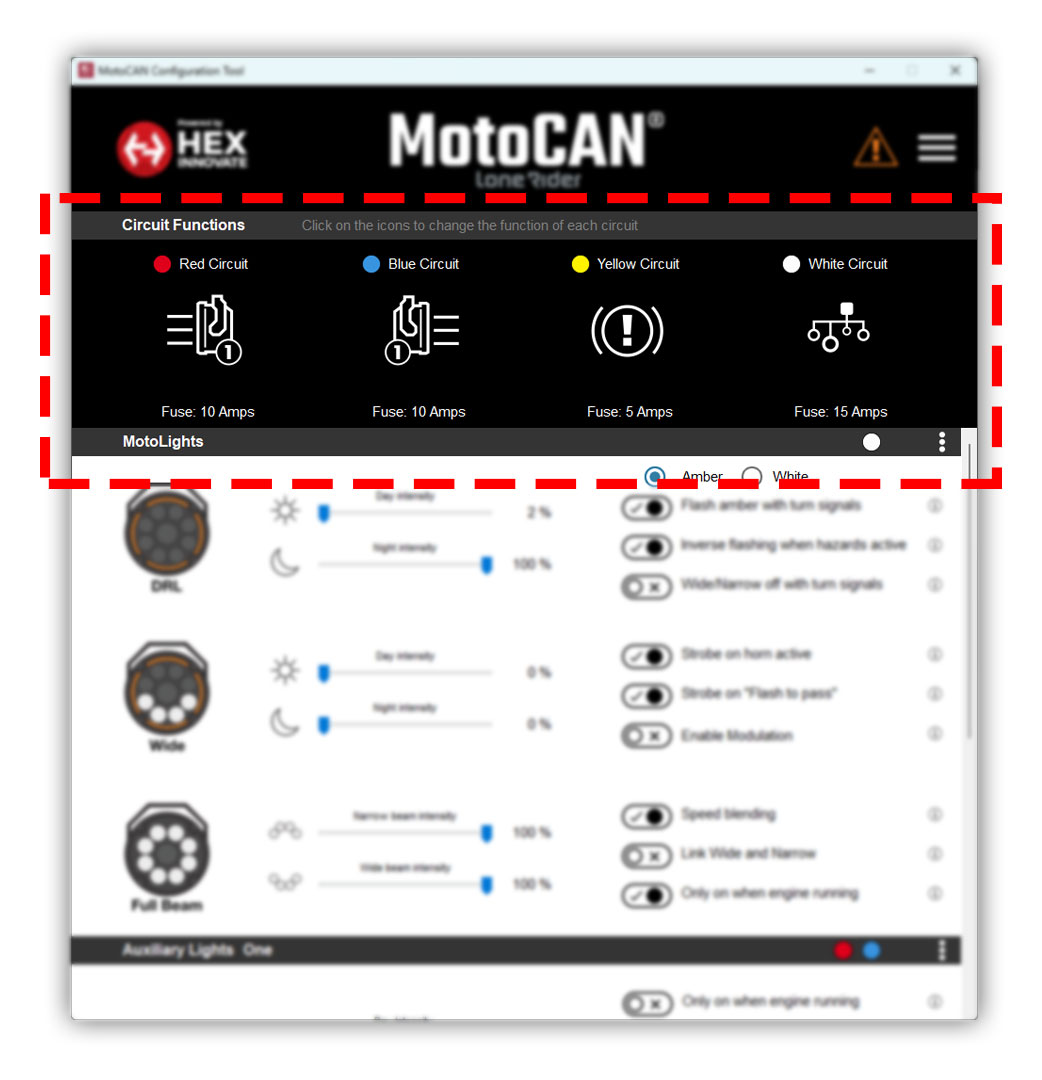
If you received four different coloured wires, please note the colour-coding on the output wires must match the colours in the output configuration you select from the MotoCAN circuit function software. Red to red, yellow to yellow, etc. Black wire is Battery Negative and the Red, Blue,Yellow and White are the Positive Supply.


STEP 6:
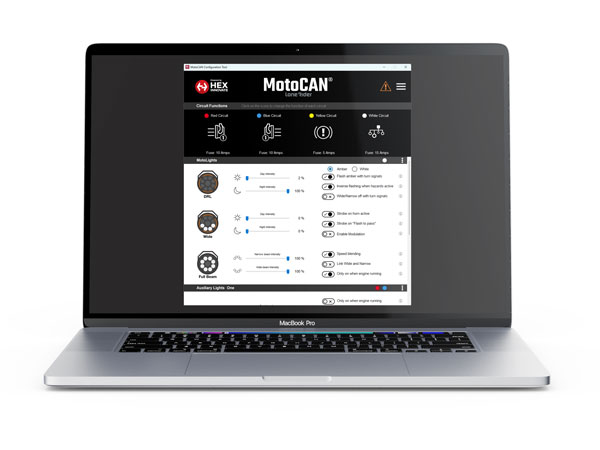
DOWNLOAD, INSTALL & CONFIGURE THE SOFTWARE
CLICK HERE TO DOWNLOAD THE SOFTWARE
Please download the 'Quick Start Manual PDF' from the software page for the most up-to-date and comprehensive installation and configuration information.

STEP 7:
TEST THE INSTALLATION
Most newly installed accessories can be tested simply with the ignition “ON”, but some brake functions will require the bike to be in motion and traveling above a certain speed. For example, emergency braking requires deceleration of more than 21km/h/s (kilometres per hour per second).
SAFETY NOTICE: Test and check your installations and accessories in a safe, controlled environment. Caution is advised at all times. Extra vigilance is required when testing new features or accessories. You do so at your own risk.
DISCLAIMER: MotoCAN is not liable for any injury or damage howsoever caused and all products and services are used at your own risk.
STEP 8:
COMPLETE THE INSTALLATION
Complete the installation by:
- Ensuring all cables and cable harnesses are secure and that the MotoCAN has a snug, secure place to rest (use the provided cable ties where required)
- Replacing the parts and screws that were removed in Step 2 (in the reverse order)
- Finally, give your installation a final inspection and a final test.
Well done! Now finish that beer whilst you read the important information in the User Manual on how to set the brightness of your lights using your bike’s handlebar controls. Did you know you can also toggle your accessory lights on and off using your handlebar controls?
Top Tip: Read section 5 of the MotoCAN User Manual!
SKU: LR-KTME-002 (Gobi) - PN.: LR0445
23OCT2024

